Kajima Airdome


General information
-
Location address
Chiba City
-
Location country
Japan
-
Year of construction
1985
-
Name of the client/building owner
Kajima Corp.
-
Function of building
Sport
-
Degree of enclosure
Fully enclosed structure
-
Climatic zone
Temperate - cold winters and mild summers
Description
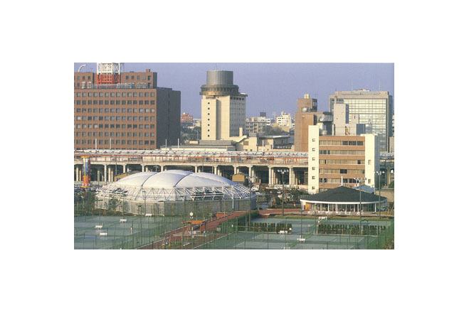
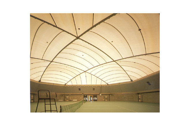
This building was constructed to house two prefectural indoor tennis courts located in Chiba City near its harbor. One of the goals of constructing this project was to develop technology which would later lead to building a large scale air dome- soon to be needed to cover an indoor baseball ground. This type of system still needed overall development. The medium-sized airdome style was rapidly growing in demand for practical indoor sports facilities which could completely fulfill spatial and formal requirements of various public organizations (such as schools).
Building Scheme
I. Realization of Low-Rise Roof Configuration
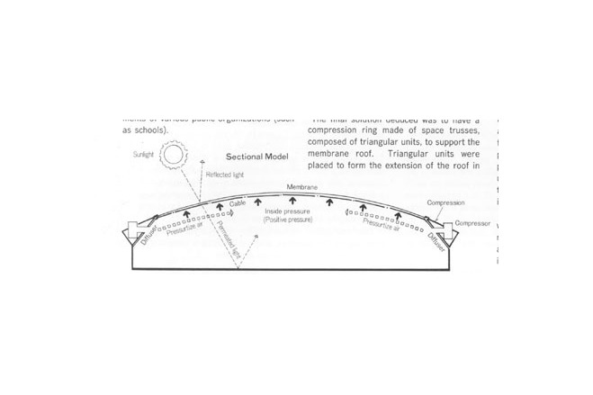
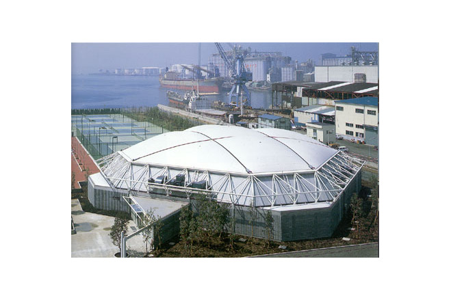
The roof configuration of air-supported membrane structures should be of a low-rise profile to receive a minimum amount of positive pressure from heavy winds , thereby avoiding deformation of the membrane roof. Tennis courts, however, require a roof height of 8m to 12m. One of the most important design objectives was to find a solution to the imbalance created by a flat roof surrounded by majestically high walls. The final solution deduced was to have a compression ring made of space trusses, composed of triangular units, to support the membrane roof. Triangular units were placed to form the extension of the roof in such a manner that the roof had a slope in its low profile and rose from the perpendicular foundation walls.
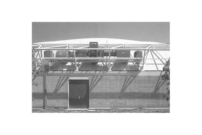
II. All Equipment into Truss Storage Space
These space trusses were not only smart and economically designed supports, but served as the storage area for various equipment needed for the continued functionability of the air dome. Equipment was contained and shelved within the truss supports. First, boards were laid horizontally inside the trusses. These boards functioned as maintenance catwalks and also as mounts for equipment. The types of equipment placed on the boards were blowers for air prssure, membrane cooling water pipes used to control solar heat, exterior air conditioning units, exhaust ducts, electrical wiring, spray nozzles, etc.
The interior of the inverted triangle trusses were plated with extruded cement boards measuring 4m in length. These functioned as roof and wall materials as well as noise insulation boards.
III. Clear-cut Structure
The airdome was composed of three components: the membrane roof, a space truss ring as its boundary structure, and the supporting substructure. As the roof and the compression ring composed one self-supporting structure, it left the substructure disencumbered of burdens except the transference of the vertical force of the roof component into the ground.
Description of the environmental conditions
Structural Plan
As stated above, this building was comprised of three components: the membrane structure roof, the space truss compression ring and the supporting substructure. They in concord created and air tight space.
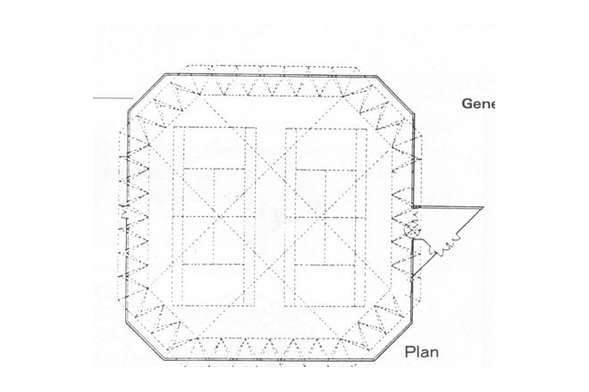
I. Cable Layout
The roof portions that covered the corners were cut off square planes measuring 32,8m x 32,8m each. The roof was composed of membrane panels divided by cables and the boundary structure. The cables reinforced the membrane dome, giving it a curvature span and rise ratio of 0,12.
The larger and simpler panel is considered far better for membrane material construction. In such a case, the strength of the membrane material and handling difficulties have to be taken into consideration. Larger panels have merits of reducing the work volume involved in panel fabrication and connecting complicated panel joints. The designers of Kajima Air Dome decided upon the most sensible choice: this type of cable layout.
II. Compression Ring
The composite of the membrane roof and the compression ring created a self-balancing system. The large space truss ring, made of steel pipes, was an ingenious way to frame, doubling its use as the substructure's top beam system as well as serving as the lower chord system of the compression ring. This area served in the additional purpose of providing storage space for equipment.
III. Concrete Block Substructure
The substructure was a reinforced concrete block wall which had been developed by Kajima Corporation and was named "KACOM Method". The outside design of the concrete blocks was ribbed. The inside portions of the blocks were filled with concrete to minimize air leakage.
[Membrane Structures in Japan, Kazuo Ishii, p108, 110]
Material of the cover
-
Cable-net/Fabric/Hybrid/Foil
Cable
-
Material Fabric/Foil
Fiberglass
-
Material coating
PTFE
Main dimensions and form
-
Covered surface (m2)
1486
-
Total length (m)
32.8
-
Total width (m)
32.8
Duration of use
-
Temporary or permanent structure
Temporary
-
Convertible or mobile
Convertible
-
Design lifespan in years
00-05
Involved companies
-
Architects
Kajima Design
-
Engineers
Kajima Design
-
Contractors
Taiyo Kogyo Corporation
-
Suppliers
Taiyo Kogyo Corporation
Editor
-
Editor
Marijke M. Mollaert