Fina petrol station in Wanlin, Belgium


General information
-
Location address
Wanlin
-
Location country
Belgium
-
Year of construction
1995
-
Name of the client/building owner
FINA Europe sa, Brussels
-
Function of building
Vehicle services
-
Degree of enclosure
Open structure
-
Climatic zone
Temperate - cold winters and mild summers
-
Number of layers
mono-layer
Description
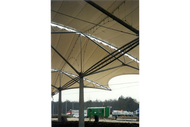
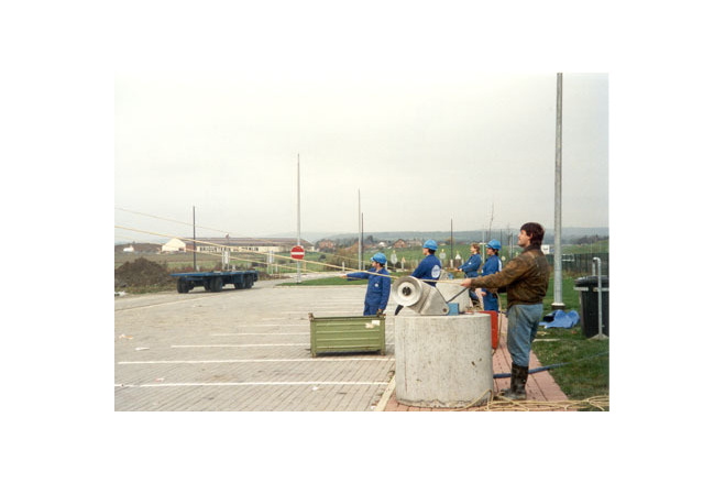
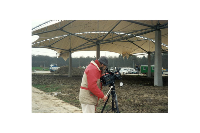
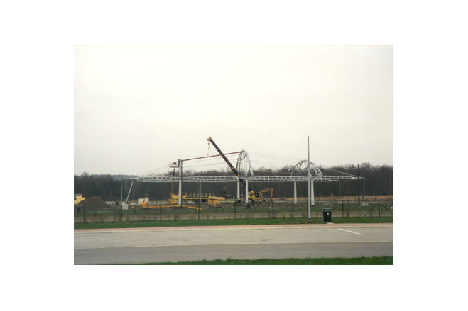
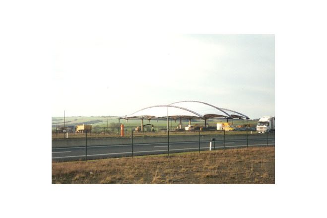
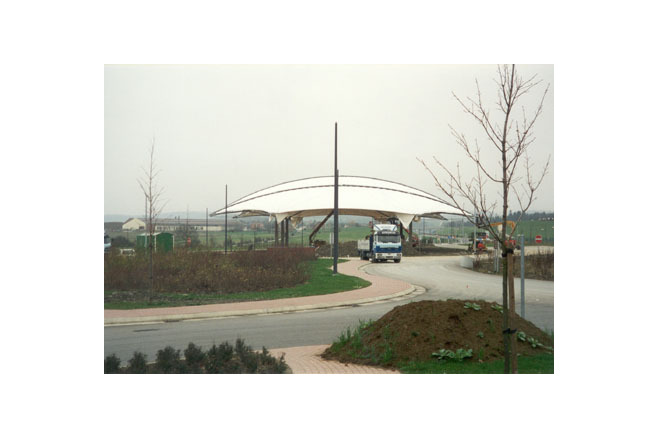
For the 74th anniversary of its founding PETROFINA wanted to erect an extraordinary, forward-looking service station. Analogous to the increased performance and comfort of automobiles these new service stations in their style have come a long way from the traditional image of a steel canopy with a colorful advertising frieze in gaudy colours along the roof edge. The site lies on the E411 between Namur and Luxembourg on both sides of the motorway and will be connected by a bridge-type restaurant to be erected by the managing company. Other areas contain the usual functions of children's playground, picnic area and car truck parking. Open terrain, fields and woods in a hilly landscape typify the site, which is exposed to the local harsh weather without protection.
Design
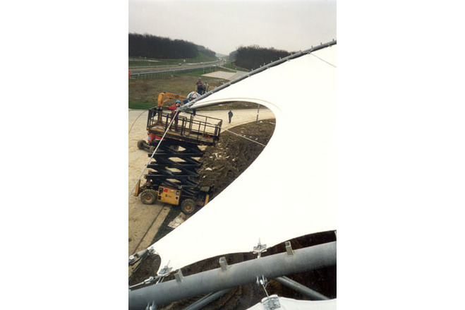
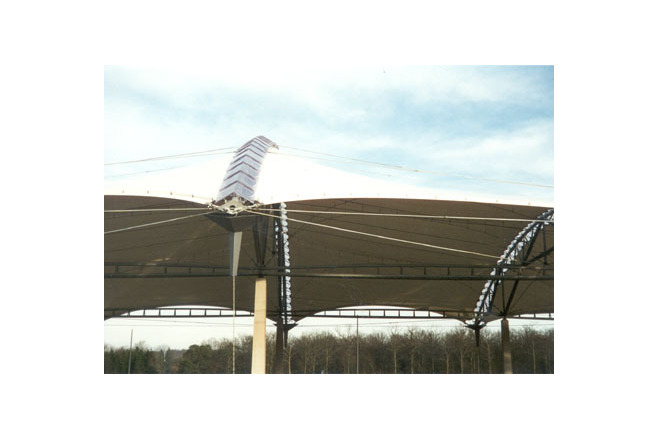
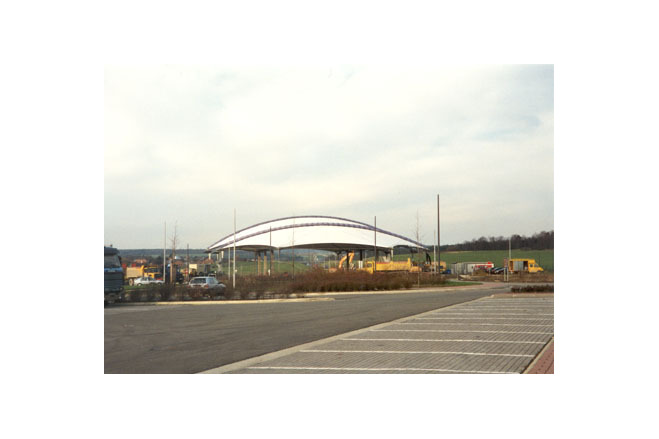
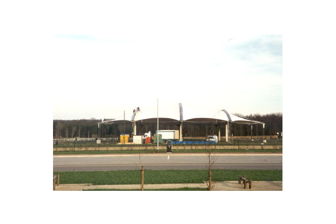
The design omits load advertising; only the totem pole and the company logo in front of the sales area show the company's name. The large glazed windows of the shop offer a view onto the grandiose landscape. In the interior of the shop a large room height provides ample space and good air quality. The large air volume reduces the need for frequent air renewal. And the overall style is quite unlike similar projects: there are no varnished or coated surfaces, but instead galvanised steel, coated fabric, anodised aluminium, wood., glass and concrete. Each of the two stations consists of a continuous translucent textile roof, 2000 m² large, which covers the whole plant including the petrol station, reception area and sales buildings, and protects costumers and visitors from sun, rain and snow. The standard landscaping, common along the motorways, of hedges and lawns is replaced by shallow, reflecting ponds, which have a balancing effect on the local microclimate. The shop and sales area was executed as a large glazed box (h = 5,4 m).
Description of the environmental conditions
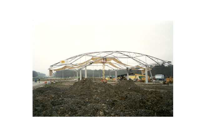
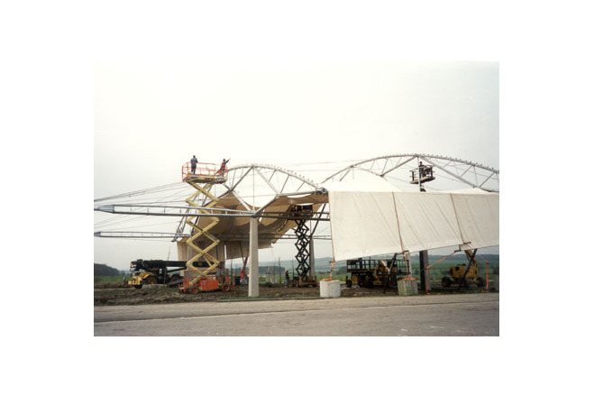
Structure
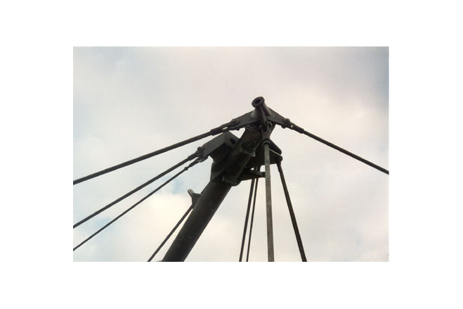
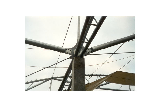
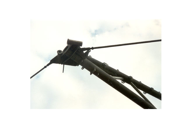
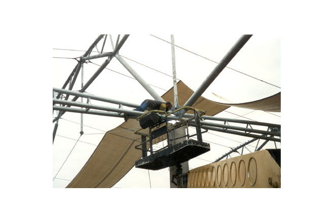
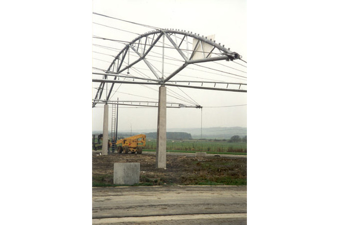
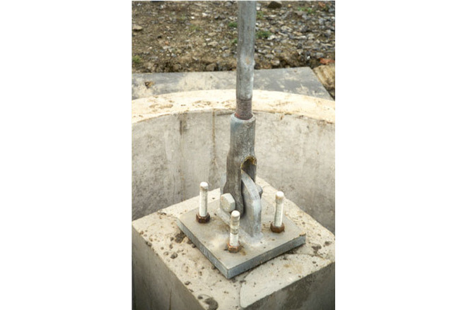
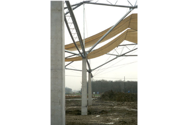
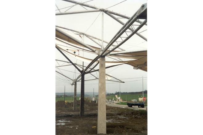
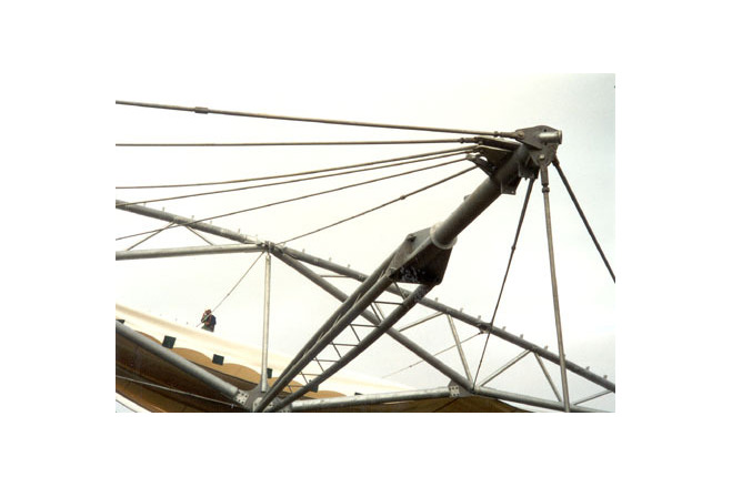
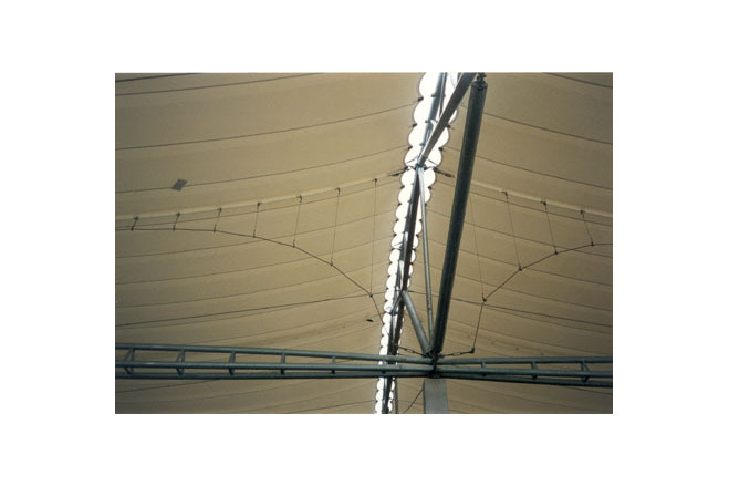
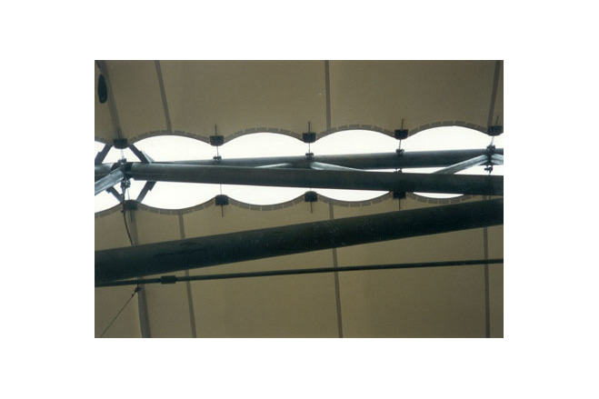
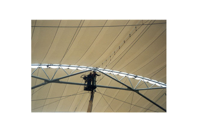
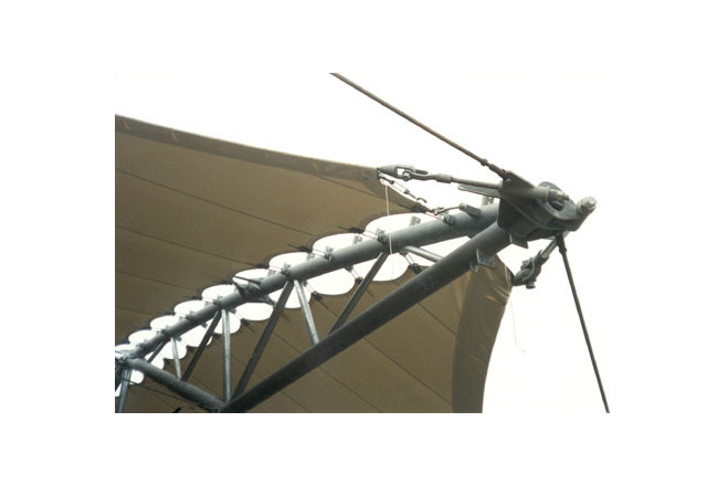
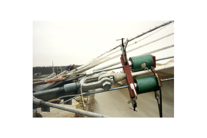
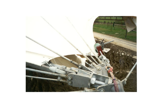
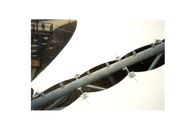
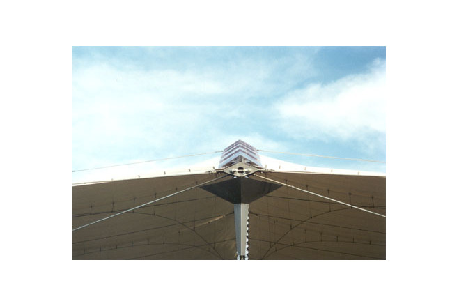
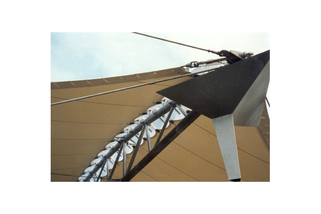
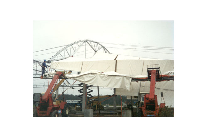
The structure under the membrane consists of 3 parts:- the roof girders,- the inner and outer compression struts, and- the tension ties joining roof girders and compression struts. The steel structure is galvanised. The main structural elements are curved truss girders, two with a length of 40 m and one 44 m long, with a rise of 4,6 and 7,0 m. They form the substructure for the membrane roof. The girders consist of partly straight, partly curved steel tubes (Ø 114,3 x 3,6 mm to Ø 219,1 x 8 mm). The roof skin is connected to the upper chords (Ø 193,7 x 5,4 mm) with adjustable threaded U-bolts and welded onto connection plates (a = 1,0 m).Each girder is supported on two 5,5 m-high concrete columns on a 20 x 15 m grid. In longtudinal direction of the roof, perpendicular to the arch girder, the column heads are connected by horizontal, three-chord tubular steel compression members with a fishbelly shape (3 x Ø 133 x 5 mm). In the end bays these compression struts cantilever out by 12 m and are , in the same way as the cantilevering arch ends, tied down and anchored by vertical tension ties. A system of round bar ties (Ø 20 to Ø 36 mm) joins the arch girders to brace them perpendicular to their plane against lateral buckling and asymmetrical wind or snow loads from the membrane. These tension ties are fastened to the ends of the cantilevering compression struts and also carry their self-weight. Due to the horizontal forces acting on the girders their upper chord members are loaded by tension and the bottom chord partially by compression, which shows in the member cross sections. Perimeter cables proceeding in chord direction of the cable edge hold and stabilse the cantilevering compression struts in a horizontal direction and carry forces in a tangential direction. Curved tension cables under the membrane are part of a lightweight cable girder which stabilises the membrane and stiffens it against wind loads. The connection between membrane and structure is covered by 252 transparent PVC shells. The steel weight of this structure, relative to the covered plan area, is 14,5 kg/m² and relatively highly, compared with other textile roofs of this kind. On the one hand this results from the flat membrane curvature, whereby relatively large forces emerge under prestress and loads. On the other hand it is due to the fact that the roof is not guyed against the foundations, but spans freely from column to column, so that the horizontal forces are transferred by the structure in plane of the roof where they are balanced. The design snow load is 0,45 kN/m². A vertical wind suction load of 1,0 kN/m² was assumed.
General comments, links
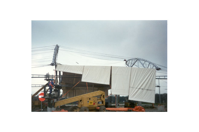
Membrane
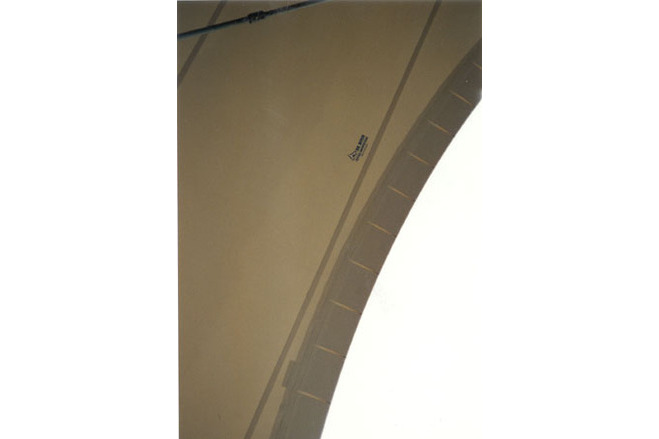
The fundamental decisions on the architectural form were made with the help of simple physical models from cardboard, nylon stocking material and thread, which could be built within a few hours. Rough order-of-magnitude calculations for the forces were later verified through a computer analysis, which was more time-consuming. The structure consists of four independent membrane elements, two inner and two edge panels. After establishing the basic geometry a computer calculation yielded excessive displacements of the membrane under extreme wind load. For the remedial stiffening of the structure three different schemes were explored: reinforcing the membrane by cables, inserted in pockets, which considered a rather expensive solution; enlarging the rise by increasing the arch curvature (I.e. smaller radius); installing a system of light cable girders underneath the membrane. The cable girder system was the preferred solution, which also left the girder geometry unchanged. The vertical cables of these girders are slightly prestressed; they do not carry a share of he snow loads. The cable girders lie partly on the axis of columns and compression struts and partly between them, in the latter case their horizontal forces are introduced into the edge cables. Under prestress the membrane stresses are 16 and 11 kN/m in weft and warp direction; under load they are 21 and 19 kN/m. For reasons of availability the used membrane is stronger than statically necessary. It consists of white PVC-coated polyester fabric with an acrylic coating on both sides; it has a weight of 1450 g/m² and a tensile strength of 8/7,8 kN/5cm in warp/weft direction (FERRARI Précontraint 1502/144, required would have been only a 1202/144 with strength of 5,7/5,2 kN/5cm). The total factor of safety is classified as difficult to ignite; (class M2 in the French code). It is manufactured in a strip width of 1,8 m, the high frequency welds are 4cm wide. The stainless steel edge cables run in cable sleeves. Through careful pattern cutting and production, wrinkling of the membrane was almost totally avoided. The compensation factors for cutting the pattern were determined as 1,10 % in warp and 1,15 % in weft direction from stress-strain diagrams from physical testing by the fabric manufacturers.
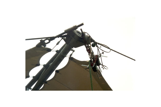
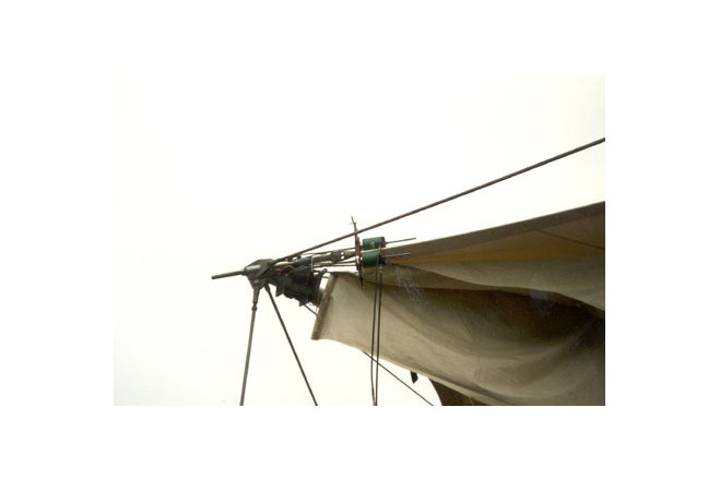
Edge, membrane corners
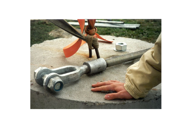
The stainless steel edge cables (Ø 12 to 30 mm) run in membrane sleeves and are continuous along the arch girder over the entire length. Corner plates are clamped onto the upper and lower side of the membrane. These plates are cut with a radius along the edge cables and connect the membrane via adjustable, threaded U-bolts and welded connection plates (a = approx. 1,0 m) with the curved upper chords (Ø 193,7 x 5,4 mm) of the trusses. At the ends of the compression struts two edge cables and up to ten tension ties are connected. The edge cables are pin-joined with a threaded bolt, running in a tube sleeve welded to the corner assembly at the end of the compression strut. Arch covering, drainage Overlapping, transparent PVC panels along the ridges of the steel arch girders cover the open garland edge of the membrane and at the same time serve as natural ventilation. Their fire performance is in the same class as the membrane. The very cost-effective PVC-material used is not fully transparent, but it is sufficient to make the steel-girder structure behind it visible. The rainwater is collected in simple membrane gutters welded along the edge cables, stiffened along their edge with thick boltrope edges and held by sheet metal angles. The water is channeled into large, triangular sheet-metal funnels, hanging at the ends of the truss girders and at the guys, guided down along vertical rain chains (no downpipe) and collected at the ground in concrete troughs. The membrane gutters at the edge also prevent snow sliding off in winter. [Soft Shells, Hans-Joachim Schock, p136, 138-140]
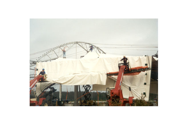
Service Station, Wanlin, Belgium
Material of the cover
-
Cable-net/Fabric/Hybrid/Foil
Fabric
-
Material Fabric/Foil
Polyester
-
Material coating
PVC
-
Weight (g/m2)
1450
Main dimensions and form
-
Covered surface (m2)
2000
-
Total length (m)
44
Duration of use
-
Temporary or permanent structure
Temporary
-
Design lifespan in years
21-30
Involved companies
-
Architects
Samyn and Partners
Setesco
-
Engineers
VUB, Afd. Arch., Faculteit Toegepaste Wetenschappen
Editor
-
Editor
Marijke M. Mollaert