Expo 1970 (Osaka): Automobile Pavilion


General information
-
Location address
Osaka
-
Location country
Japan
-
Name of the client/building owner
Japan Automobile Manufacturers Association, Inc.
-
Function of building
Exhibition
-
Degree of enclosure
Fully enclosed structure
-
Climatic zone
Temperate - cold winters and mild summers
-
Number of layers
mono-layer
Description
Outline of Pavilion and Exhibit
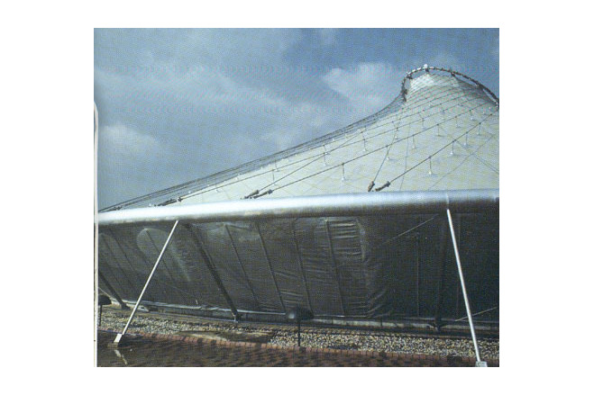
The pavilion was sponsored by the Japan Automobile Association and comprised two pavilions and an outer plaza. Each pavilion was erected on a circular plane but its center was eccentrically located. At each eccentric center a cylindrical tower, 8 m in diameter, with top cut diagonally, was erected. Cables were hung from the top to the peripheral ring and from these cables the membrane was suspended.
The first pavilion had a diameter of 40 m and a height of 25,4 m. the second pavilion had a diameter of 45 m and a height of 17 m.
The No. 1 Pavilion was used to introduce the exhibition theme, "World of Rhythm" and to serve as foyer to the No. 2 Pavilion. Inside there was a sculpture made from automobile engines and engine parts that were mounted to a height of more than 10 m to symbolize rhythm. The No. 2 pavilion featured an extra wide movie screen which showed a movie titled "24 Hours a Day". The movie film was projected onto three large consecutive screens and up onto the ceiling. Both pavilions were designed to provide a large, pleasing space with a relaxing atmosphere despite the hustle and bustle of many visitors moving throughout the pavilions.
Description of the environmental conditions
The Framing Method of the Pavilion
In order to pursue a common configuration and structure for both pavilions, based on the exhibit plan, a barnacle-shaped construction was created. In order to form such a configuration the following construction methods were studied.
a. configuration the following construction methods were studied.
b. Reinforced concrete shell structure
c. Suspension membrane structure
d. Cable net suspension structure covered with reinforced concrete slabs and metal plates
e. Suspension membrane structure with cable network
After carefully considering constructability, safety, and economy from the view point of the structure's temporary purpose, the above method(e) was chosen: a suspension membrane structure with cable networks. The configuration was made by one sheet of membrane, curve to form the cone- atype of hyperboloid emerged. The tensile force was introduced to a maximum extent so as to suppress fluttering within the membrane fabric.
Structural Elements and Materials
From final structural analysis the two aforementioned pavilions were composed of the following major structural elements.
1) Peripheral Rings
Peripheral rings to which the lower parts of wire ropes were fixed. The first pavilion was based on a ring measuring 39,4 m in diameter. The second pavilion was based on a ring that measured 45,4 m in diameter. The diameter of the steel pipe that was used for the ring was 457,2 Ø (STK41). The ring was anchored to a reinforced concrete foundation through 24 rectangular trusses placed around and fixed to the ring.
2) Cylinder shaped shafts
The pinnacle of the shafts, which were actually cylinder shaped pillars, were used to support an apex ring. All of the upper ends of the wire ropes were fixed to the opening. The shafts measured 25,4 m in height for No. 1 Pavilion and 17,0 m in height for No. 2 Pavilion and both 6,8 m in diameter. The shafts were located at the eccentric center of 1: 3 from the outer edge of each pavilion's circular base. The structures were space frames which were made from H shape rolled section/steel beams (SS41).
3) Cable Network
The cable network comprised an apex ring and peripheral ring which were wired using 96 pieces of wire rope (20Ø grade 4Z, hard steel wire) to form a deformed hyperboloid. A single sheet of vinylon membrane was suspended from the network. The initial tensile force introduced to each cable had to be powerful enough to counter the lifting force from the winds of up to 20 m/sec velocity. The wiring was adjusted to also minimize the imbalance in the horizontal component force at the top of the shaft. In addition to these factors, the network was required to cope with the climatic stresses of typhoons. Intersections of cables were supported and fixed by sub-cables, and the whole structure was anchored to reinforced concrete foundations under the ground. The sub-cables, when connected to the main cables, worked to suppress deformation of the main cables and to prevent an increase in the stress at boundary due to fluttering.
4) Fabric
PVC-coated Vinylon fabric (KV #71000, 1 kg/m²) was used for the roof membrane. The fabric was suspended from the cable network using metal hangers. The hangers were placed at intervals of less than 3 m.
[Membrane Structures in Japan, Kazuo Ishii, p 22-25]
Material of the cover
-
Cable-net/Fabric/Hybrid/Foil
Cable
-
Material Fabric/Foil
Vinylon
-
Material coating
CSPE
Main dimensions and form
-
Covered surface (m2)
3445
-
Total length (m)
45
-
Total width (m)
45
Duration of use
-
Temporary or permanent structure
Temporary
-
Convertible or mobile
Convertible
-
Design lifespan in years
00-05
Involved companies
-
Architects
Kunio Mayekawa Architect and Associates
-
Engineers
Yokoyama Consulting Engineers
-
Contractors
Editor
-
Editor
Marijke M. Mollaert