Olympic Games 1972 (Munich): Olympic stadium


General information
-
Location address
Munich
-
Location country
Germany
-
Year of construction
1972
-
Name of the client/building owner
Olympia-Baugesellschaft mbH
-
Function of building
Stadia
-
Degree of enclosure
Fully enclosed structure
-
Climatic zone
Temperate - cold winters and mild summers
Description
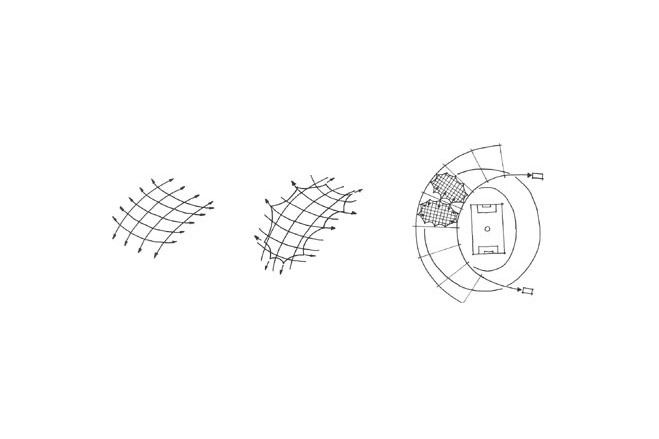
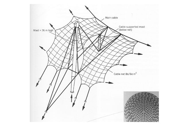
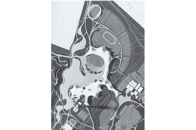
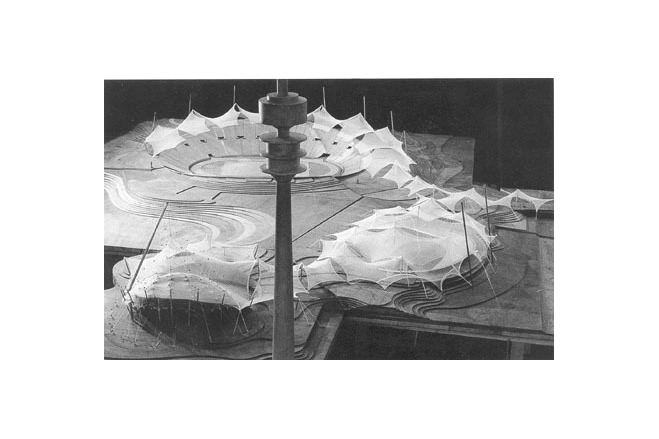
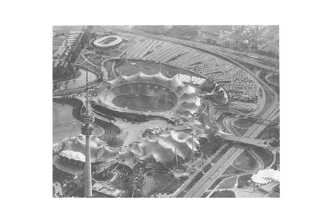
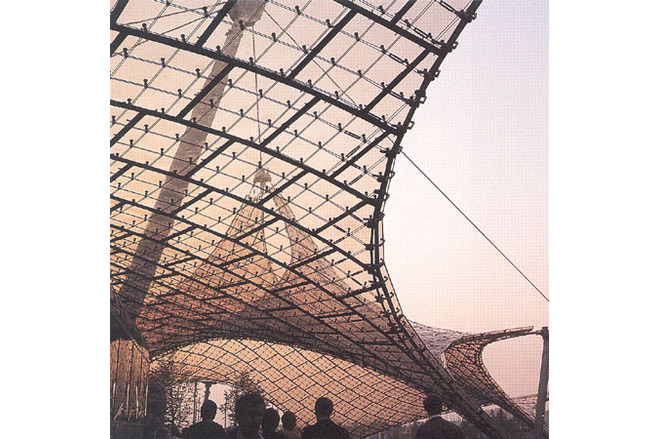
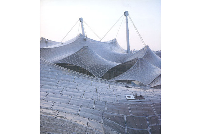
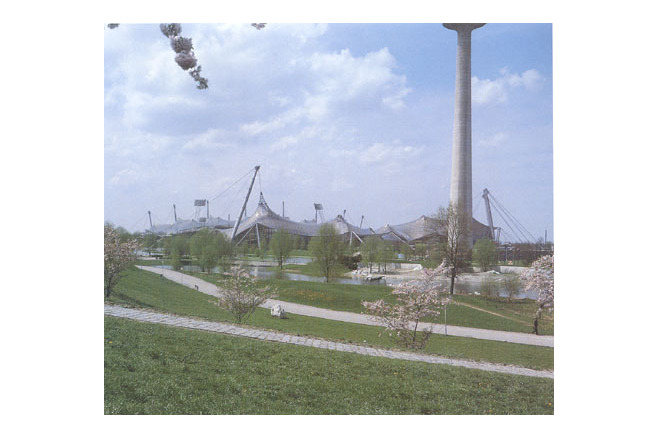
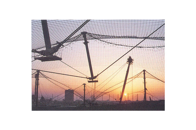
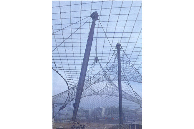
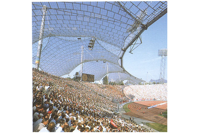
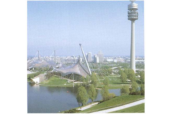
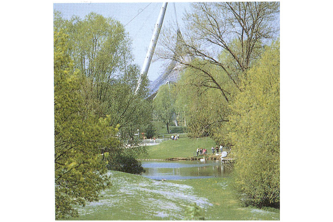
Olympic parc roofThe design competition for the 1972 Olympic Games was won by Günther Behnisch & Partner with a spectacular proposal for a continuous, undulating translucent roof covering nearly 80000 square metres of landscape. The stadium, pool and arenas were conceived nait as individual buildings but as a series of moulded earth forms sheltered by silvery lightweight umbrellas. After the Games were over this imaginatively reclaimed airfield would be open to the public as an undulating, grassy park for everyday recreation and pleasure.Initial concept To avoid rigid, rectangular shapes emerging from the design process, as tends to happen when planning is done by means of drawing boards and T-squares, Behnisch and his team evolved the basic design concept using the softest and most malleable of all media: a sand model.For the protecting umbrellas Behnisch wanted the kind of lightweight, translucent skin used at Expo '67. He therefore brought Frei Otto and Leonhardt & Andrä into the design team. The original competition design showed a single large roof supported by a few masts, and anchored at the edges. The undulations of the roof were sharply curved near the masts, afording these areas the necessary stability against snow and wind loads, but almost flat (and therefore susceptible to flutter) near the roof edges.The team's efforts to solve this problem produced lessons that are applicable to all large nets. Increasing the mast heights would give tighter curvature near the masts, exactly where it was not needed, but would leave the unsatisfactory flat perimeter areas unimproved. Increasing the pre-stress to the flat areas would provide the necessary stability, but only at impossibly high levels of tensioning. The only practical solution was to subdivide the continuous roof into a patchwork of separate but coupled smaller canopies, supported at many points and mostly curved to suitably tight radii.In the revised design the roof nets no longer extended to the tops of medium-height masts, but were hung instead from very tall masts by sets of cables. The masts were either placed outside the roof or suspended above ground on cables to keep the areas below column-free.Design developmentIn the early 1970s sophisticated computer programs were not yet available for cable-net surface design. As with the Expo '67 designs, mathematical calculations had to be based on preliminary form-finding using physical models - though the large, permanent Munich roofs posed a much more difficult design challenge than the temporary canopies at Montreal.The design development process therefore started with the construction of 1:125 scale models theat were exactly proportional both in geometry and in elasticity to the envisaged full sized structures.This was followed by an intensive programme of more detailed model-making, computation and verification, made all the more impressive by the fact that the team was moving into virtually unexplored territory, almost making up the science as it went along. Calculation of the exact geometry required special computer programs developed only just in time by Proffessors K. Linkwitz and JH Argyris.Finally, workshop drawings were produced, showing the correct configuration of every square metre of canopy surface - an exhausting task resulting in 3800 square metres of 1:10 drawings for 74800 square metres of roof area.
Description of the environmental conditions
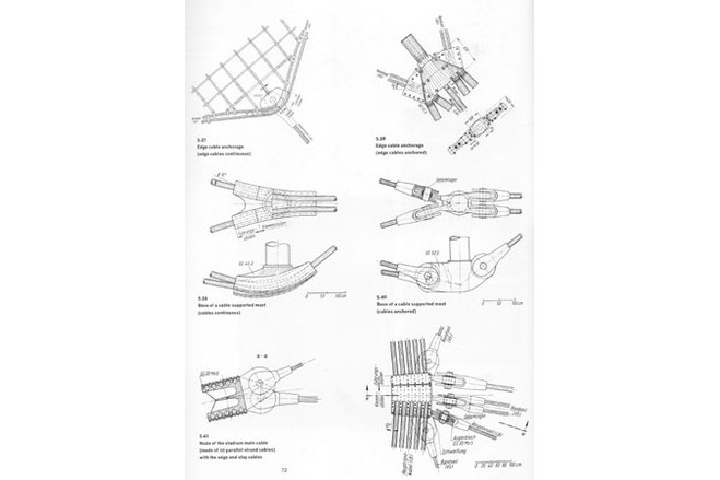
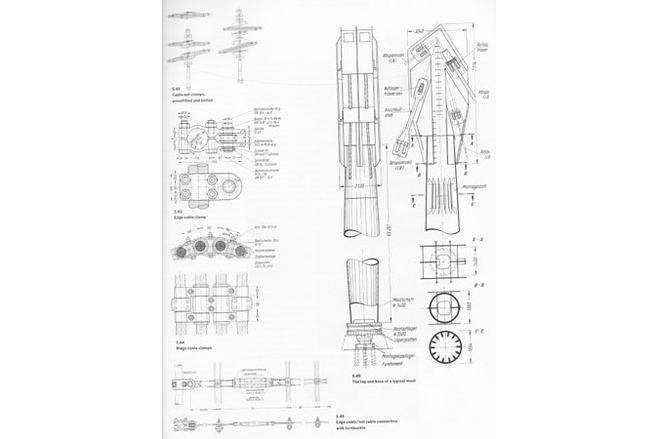
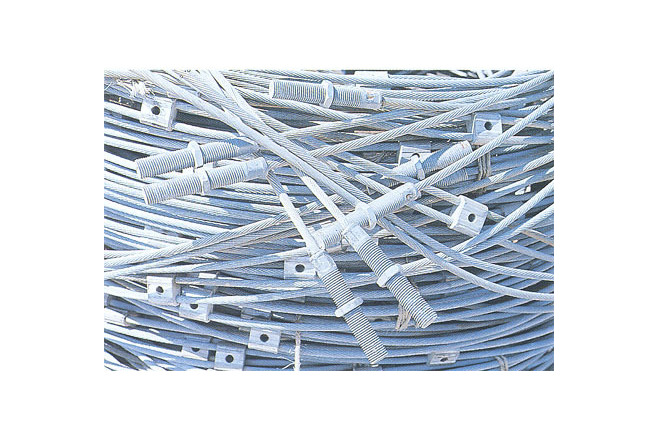
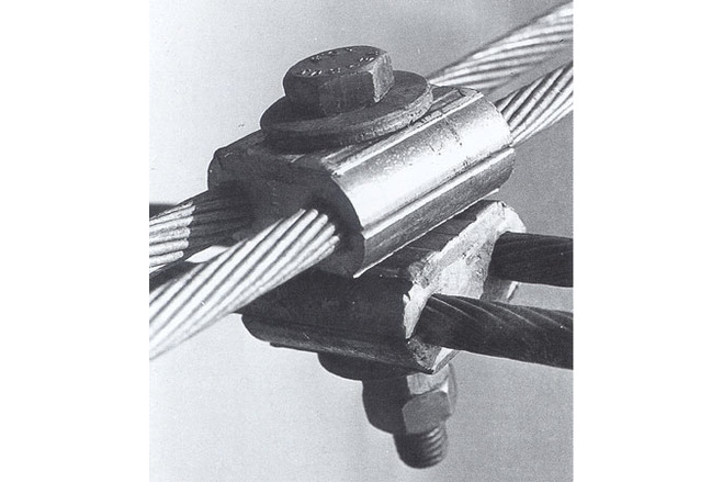
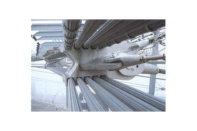
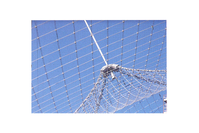
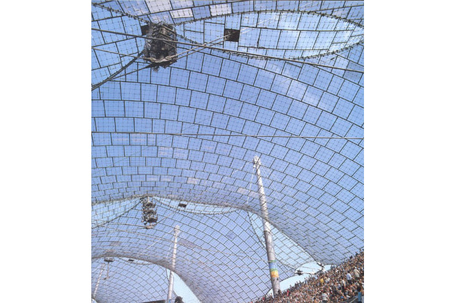
The cable netAs built, the nets are formed of crossed pairs of strands spaced 750 millimetres in both directions - a relatively narrow spacing with many advantages including safety and convenience for workmen. This spacing remains constant regardless of net shape, all changes of plane in the duble-curved surfaces being accomodated by changes in the strand intersection angles.Intersections joints were formed by an automatic process, aluminium clamps with central holes being pressed on to all strands at exactly 750-millimetre centres under a defined level of pre-stress. The two sets of strands could thus be formed into a 750 x 750-millimetre mesh with no need for measurement, simply by connecting the aluminium clamps. The connections used one bolt per joint, resulting in a freely rotatable node that allowed the mesh to adjust to any angle of intersection.With regard to cable specification, a balance had to be struck between the need for cable flexibility (which favours a strand spun from many thin wires) and durability (which favoursone spun from fewer thick wires). The decision was to form the net from strands spun 19 heavily galvanised 2,3- and 3,3-millimetre steel wires, with a lay length of 10 x the lay diameter.Main and edges cablesThe main cables, composed of five strands formed from between 37 and 109 wires each, had to be held at high tension to control deformaton of the roof under snow and wind loads. Permissible load was 11,5 mN (1150tonf); where forces exceed this figure several ropes were coupled rather than increasing cable size.The edge cables vary in specification, a typical example being a locked-surface wire rope of 81 millimetres diameter. With a safety factor of 2 the permissible load is 3mN (300tonf) and again several ropes are coupled where forces exceed this figure.Foundations and mastsTension foundations were needed to anchor the main cables down to earth. Upward pulls of up to 50mN (in the case of the big edge cable of the stadium) are exerted on such foundations, and three foundation types were used:- inclined slot foundations, working rather like tent pegs;- gravity anchor foundations, deriving their anchoring effects from self-weight plus the weight of the soil surcharge;-earth anchor foundations were needed to support the masts. To accommodate some movement these footings consist of rubber bearing pads on concrete bases. Temporary steel balls were provided under the rubber pads to allow rotation during assembly.Masts are cylindrical welded steel tubes up to 80 metres long and with a 50mN (5000 tonf) load capacity.Roof coveringThe transparent roof covering was formed of 2,9 x 2,9-metre acrylic panels of 4 millimetre thickness, laid on the cable net and bolted to the intersection nodes. As the angles of intersection in the cable net change up to 6 degrees under load and temperature change, the rigid acrylic panels had to be flexibly connected to the net. This was done by supporting the panels on neoprene pesetals, allowing them to 'float', and sealing the joints between panels with a continuous neoprene profile clamped to the panel edges. The strip had to be thin and wide enough to absorb movements by wrinkling - unfortunately an inelegeant detail.
General comments, links
Erection on siteThe cable nets were completely assembled on the ground, then lifted to their final positions. For pre-stressing, the suspension cables were first put in position, then the geometry and stresses in all cables and masts were checked. Errors in stresses of ± 15 per cent were generally accepted if analysis showed these to be compatible with the stability of the structure, while larger errors could be corrected by using turnbuckles to shorten or lengthen the cables.Thanks to the extensive structural calculations, exact pattern generation, and accurate fabrication, few on-site corrections were necessary.ConclusionBecause it was a pioneering advance into new technology the Munich roof was expensive. Moreover, it is cluttered with thousands of obstrusive fixings between crossing cables, and seems to have dauntingly over-scaled connections and anchorages. Local overheating also occurred under the plexiglass roofs, requiring the fitting of an insulating lower layer. However, these are minor blemishes on what is undoubtedly one of the outstanding architectural achievements of the century.[Cable nets, Maritz Vandenberg, p71, 72, 74, 76, 78, 80]www.structurae.de/en/structures/data/str00382.php
CBLIA 7-8
Munich '72. Jeux Olympiques
The Art of Structural Engineering: The Work of Jörg Schlaich and his Team
Olympic Park Roof, Munich
Material of the cover
-
Cable-net/Fabric/Hybrid/Foil
Cable
Main dimensions and form
-
Covered surface (m2)
74800
Duration of use
-
Temporary or permanent structure
Temporary
-
Convertible or mobile
Convertible
-
Design lifespan in years
00-05
Involved companies
-
Architects
Günter Behnisch & Partner
Leonhardt & Andrä
Editor
-
Editor
Marijke M. Mollaert