Gerry Weber Stadium
General information
-
Location address
Halle
-
Location country
Germany
-
Year of construction
1994
-
Function of building
Stadia
-
Climatic zone
Temperate - cold winters and mild summers
Description
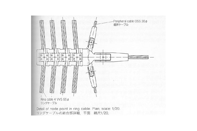
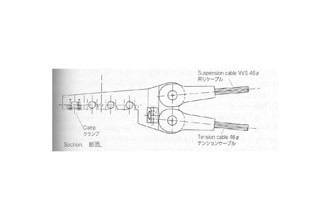
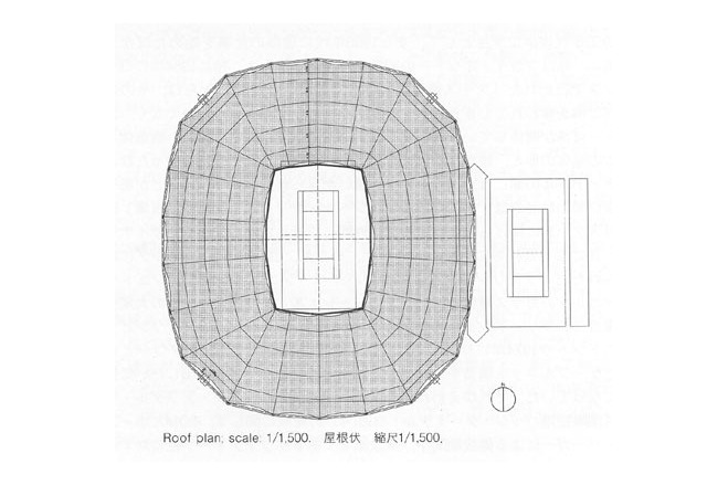
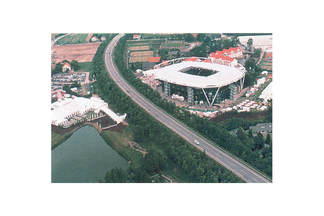
The aim to design a filigree light roof led to a structure with radial cable trusses, prestressed between two outer compression rings, and one inner tension ring. Since the grandstand design had been finished without considering a roof, its foundation also had to be placed separately outside the stadium.
The significant points of the structure are;
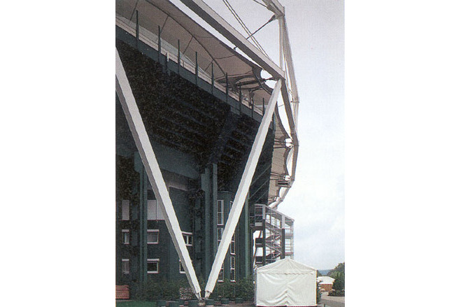
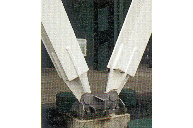
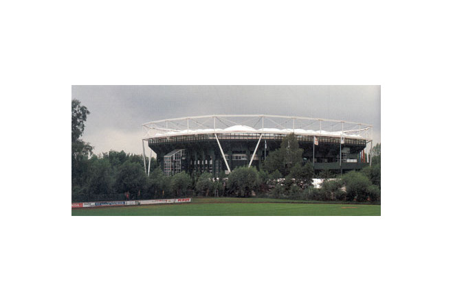
The "Court yard no. 1", placed along one side of the "Center Court", prohibited a uniformly distributed column arrangement. Therefore only two corners; they are inclined and therefore can transfer not only vertical but also horizontal forces from the roof down to their commmon foundation.
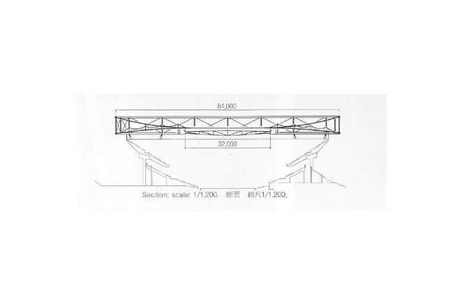
The two compression rings do not only balance the horizontal forces of the cable trusses by their curvature in plan, but act also as chords of a vertical truss girder, which due to the large column spacing transfers the vertical forces of the cable trusses to its support.
In order to adapt the inner roof openeing as far as possible to the rectangular lawn court (25 x 40 m), two cable trusses each were concentrated onto the four corners of the tension ring, and by prestressing these 4 x 2 cable trusses much higher, the desired inner roof edge geometry was gained with very large angles in its corners. The roof width of 28 m is constant all around.
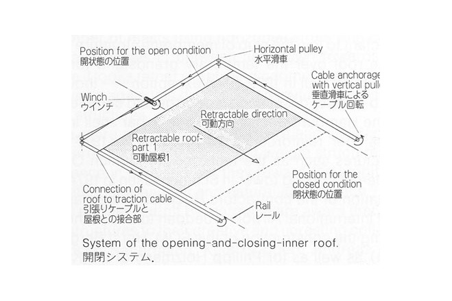
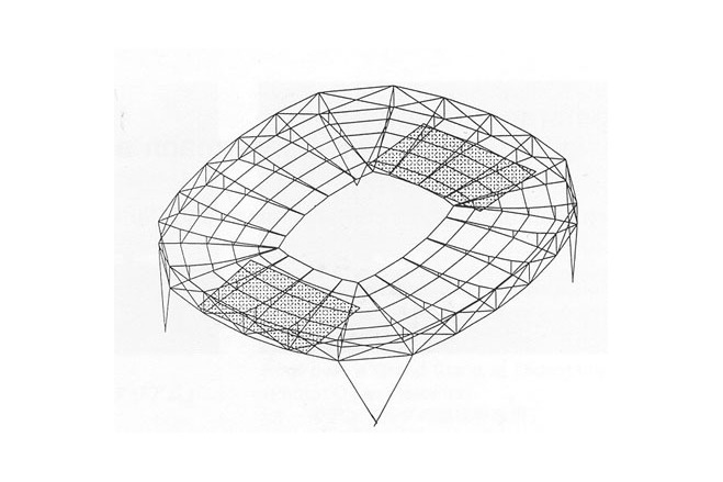
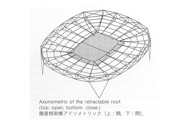
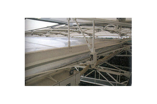
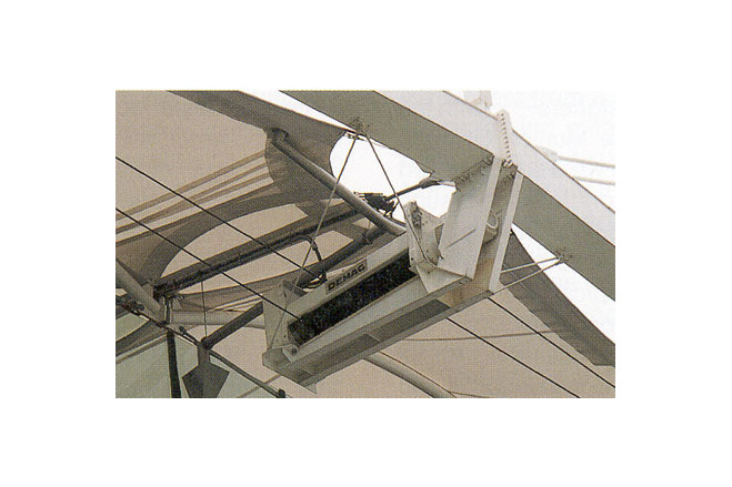
The permanent outer roof is complemented by a retractable inner roof. Parallel to the inspection walkways, two rails with a distance of 32 m are suspended from the roof, on which two nearly horizontal inner roof panls move from their parking position under the permanent roof towards the center, until they meet and completely close the opening.
Design criteria for the inner roof were;
To close the inner roof very quickly, since the lawn cannot be even light humidity. This problem was solved satisfactorily with a closing period of 1,5 minutes only.
The roof should be kept transparent in order to maintain the same impression with closed as well as with opened inner roof. This was guaranteed by a filigree steel structure and long-span pneumatically stabilized cushions made from transparent membranes.
Permanent Membrane Roof
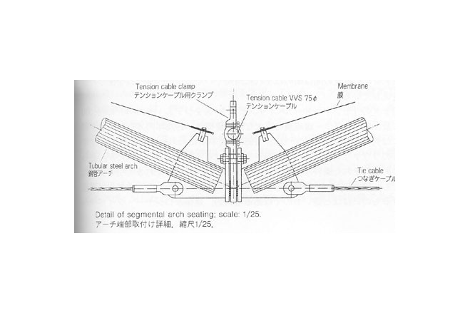
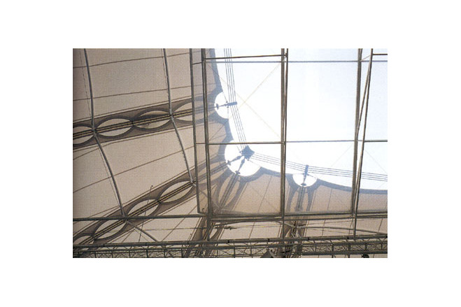
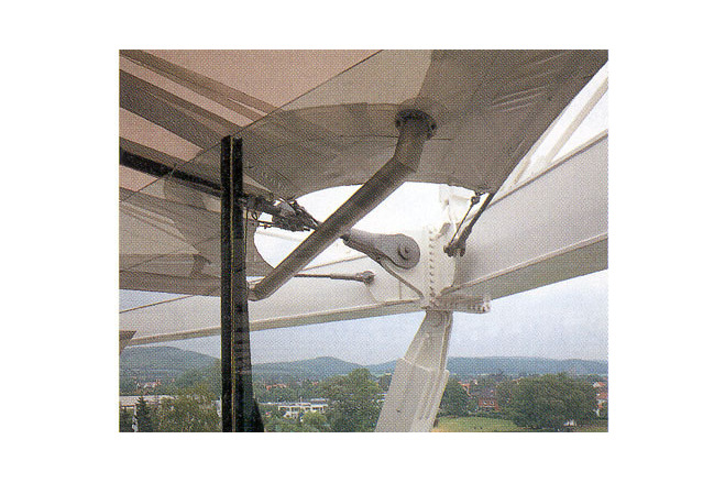
The secondary structure consisting of steel pipe arches and membranes is suspened from the prestresed cable trusses of the primary system but which is stable in itself.
Each of the 22 membranes is placed over 4 arches each, such that between the arches and the edge cables 5 sadle-shaped areas develop. The membrane does not only load the arches by its prestress and loads, but it also stabilizes them in vertical as well as horizontal direction like springs.
Retractable Membrane Roof
The retractable roof for the Center Court in Halle is moved by a simple mechanism. One winch per rrof half, using a system of deviation wheels and cable fixed points, moves one complete roof panel in both directions.
A number of switches along the rail and in the winch itself guarantees the exact parking position for the open and the closed condition.
The inner roof consists of 5 steel trusses spanning 32 m with a depth varying from 0,5 m to 1,9 m. They are connected by light diagonal cables and slender chords, totally forming a rigid roof panel with adequate stability. Air-stabilzed cushions (5,5 x 32 m) are spanning between girders. Two layers of transparent ETFE foil are stabilized by a permanent internal pressure, and thus with a common rise of 1,5 m in cross direction are able to transfer all wind loads.
The cushions-internal pressure is produced and maintained by a continuously working, specially noise-insulated ventilator.
(Schlaich, Bergermann and Partners)
[Membrane Designs and Structures in the World, Kazuo Ishii, p104-105]
Description of the environmental conditions
Material of the cover
-
Cable-net/Fabric/Hybrid/Foil
Fabric
-
Material Fabric/Foil
ETFE-foil
Main dimensions and form
-
Covered surface (m2)
6000
-
Total length (m)
28
Duration of use
-
Temporary or permanent structure
Temporary
-
Convertible or mobile
Mobile
-
Design lifespan in years
00-05
Involved companies
-
Architects
schlaich bergermann partner
-
Engineers
schlaich bergermann partner
-
Contractors
Carl Nolte GmbH & Co
Editor
-
Editor
Marijke M. Mollaert


